The Eyecad VR user interface is divided into 15 TABs (work areas organized by functions) and three kinds of styles project visualization.
1. Modify
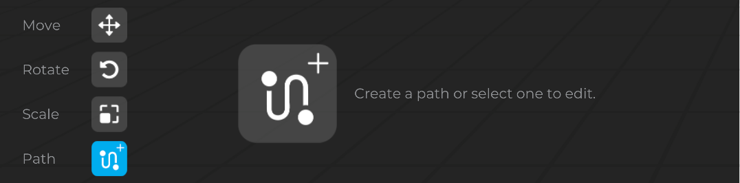
The “Modify” TAB allows you to interact through the three fundamental transformers of the 3D software, which are articulated in the commands:
 Move
Move
The “Move” command allows you to change the position of an object in the scene, varying the x, y, z coordinates of its center (pivot). The selection of the command activates a gizmo (x, y, z) that it is used to carry out a precision control, bound to one or more reference axes. The “Move” command allows you to set a shift by changing the reference coordinates in “Absolute” or “Relative” mode.

 Rotate
The “Rotate” command allows you to change the rotation of an object In the scene. The selection of the command activates a gizmo (x, y, z) that it used to carry out a precise control of the effects of the rotation to a single axis. It is also possible to enter a numerical value equivalent to the rotation angle.

 Scale
Scale
The “Scale” command allows you to modify the scaling of an object In the scene. The selection of the command activates a gizmo (x, y, z) that it is used to carry out a precise control of the effects of the scaling to a single axis. Using the unique XYZ function, the scaling occurs uniformly according to the three reference axes and it is possible to keep the proportions of the object unchanged regardless of its final size.

Path
The “Path” command allows you to create multiple instances of an object in the scene. The selection of the command activates the “path drawing” and thanks to its, is possible to create a path point by point. Once the paths has been created, is possible to configure it.
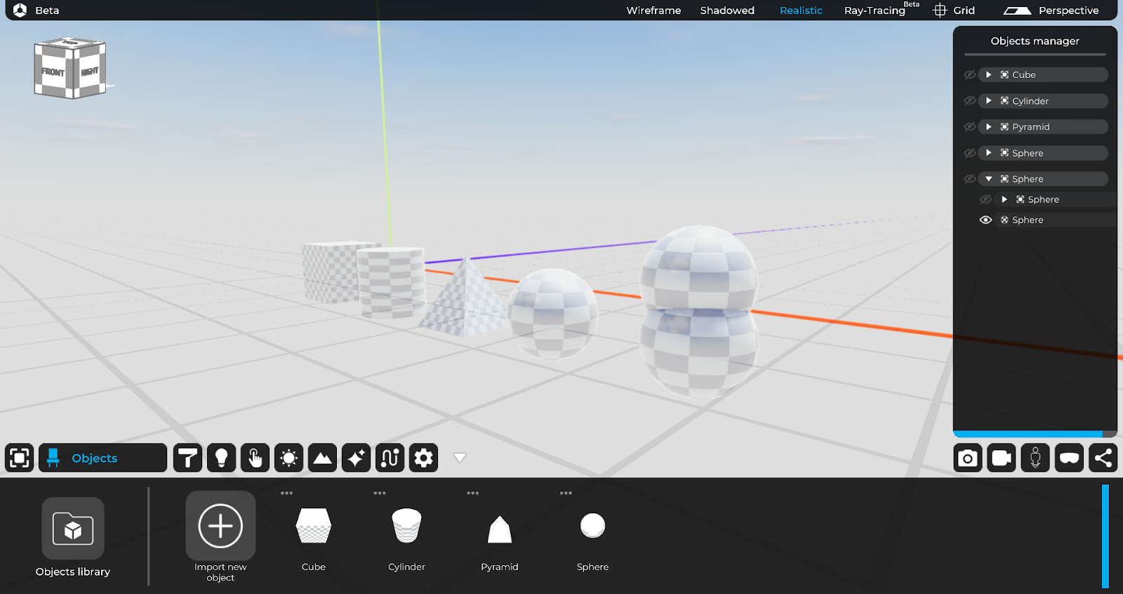
2. Objects
The “Objects” TAB allows to insert inside the project both the objects (3D models) imported from the outside and the objects inside the Eyecad VR 3D library.
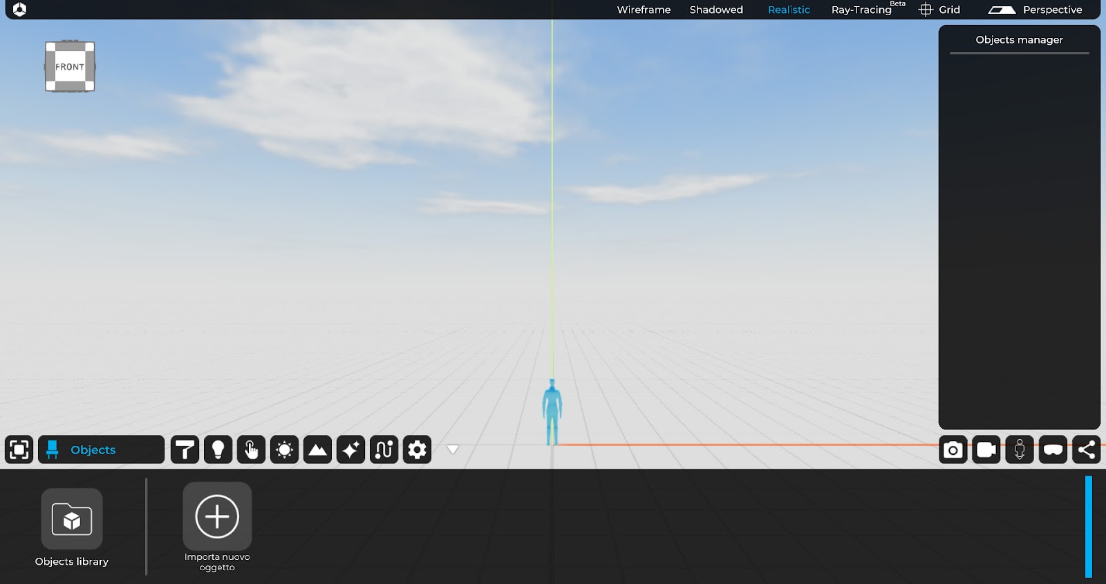
The Eyecad VR 3D objects library is composed of a sliding menu that can be used to choose the type of object, with the possibility of inserting them in the current project.
All the objects loaded in the current project are summarized in the “Objects” TAB, located on the right inside of the library menu, where it is possible to add them inside the scene through a drag and drop operation (from the folder to the 3D grid).
2.1 Import new object
The “Import new object” command allows you to add inside the project any type of object (3D model) that it is not included in the software’s proprietary libraries. You can import files with the following formats:
- Autodesk (.fbx)
- 3ds Max (.3ds)
- Collada (.DAE)
- Object (.obj)
- SketchUp (.Skp)
For a detailed overview of the options related to the importing tab, please refer to chapter 2 of this manual.
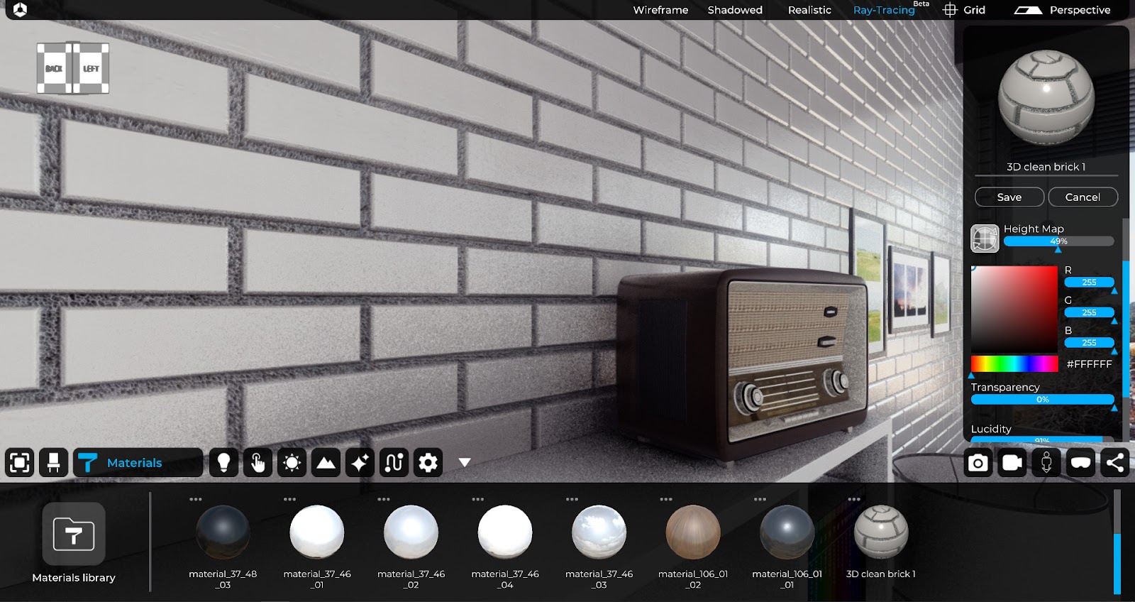
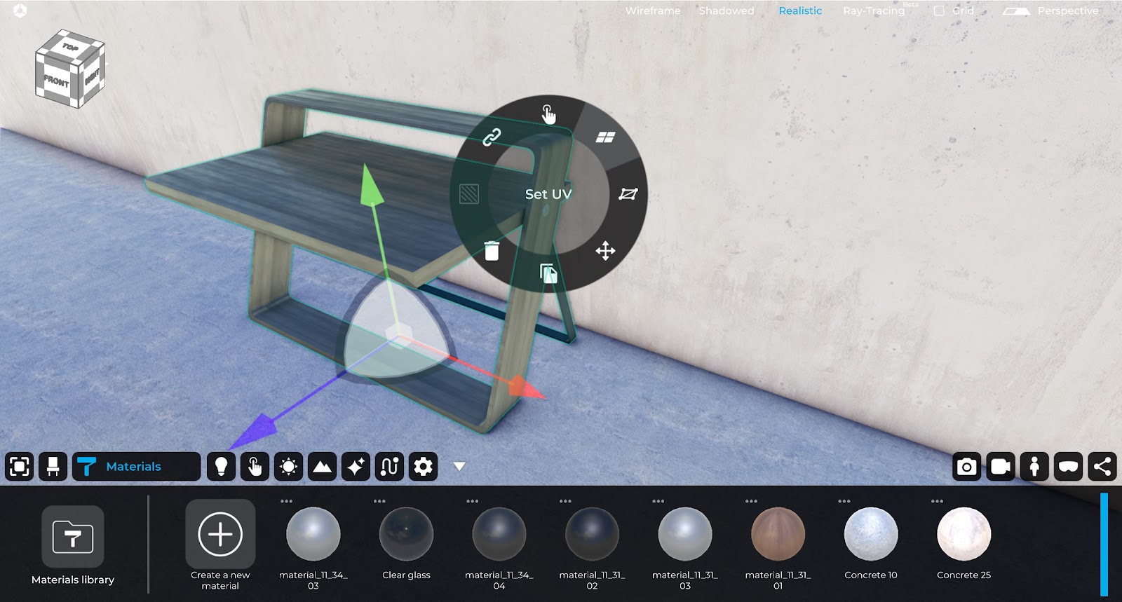
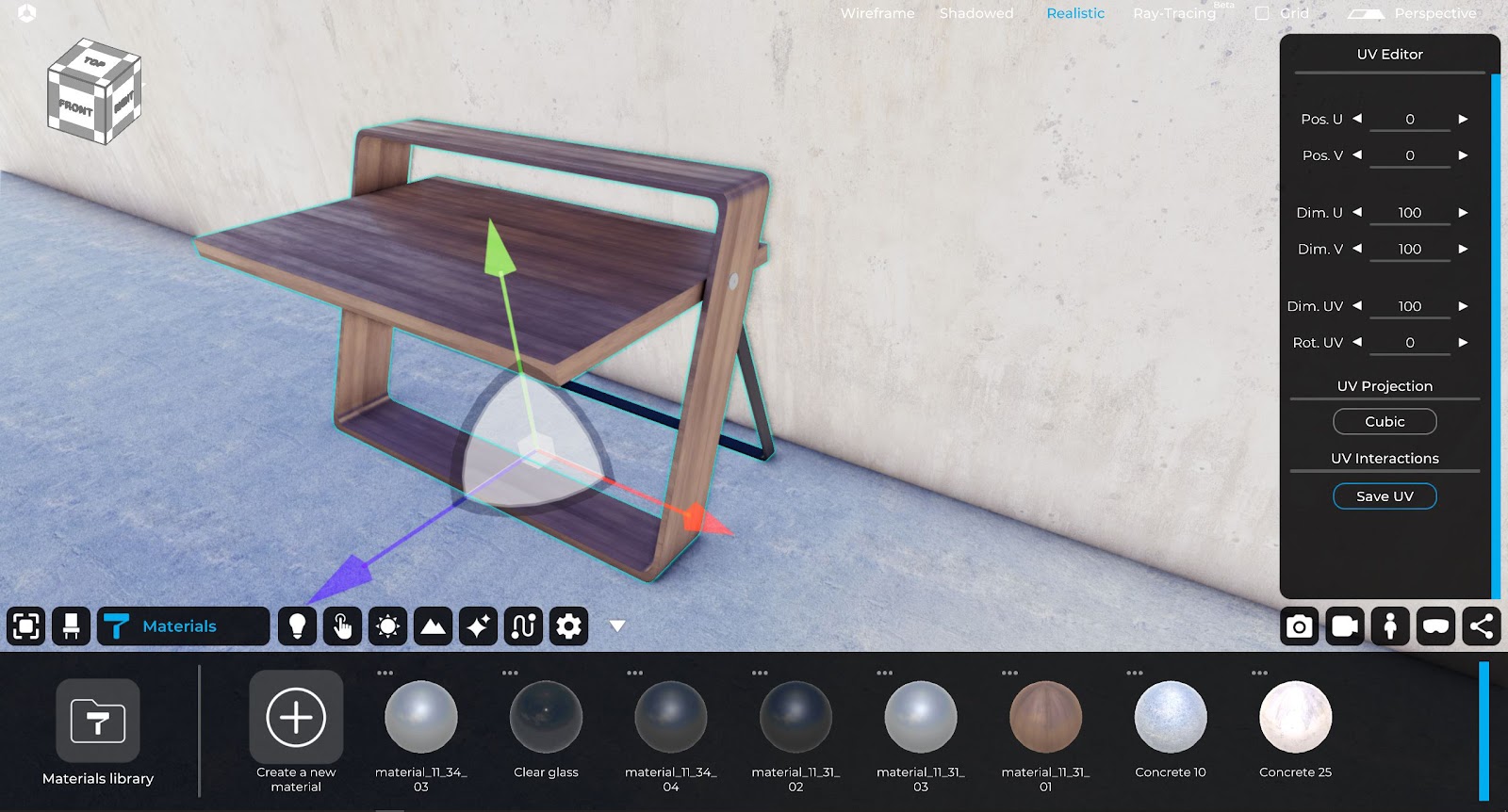
3. Materials
The “Materials” TAB allows you to manage the Eyecad VR library of PBR materials and those defined directly by the user, which can be managed in the dedicated area.

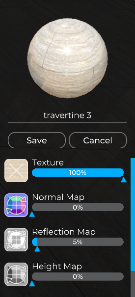
3.1 Personal Materials
The “Personal Materials” area allows you to create and customize all aspects of Eyecad VR materials, thanks to the functions provided by its editor.
To define a new material In the current project, you can click on the “Create new material” icon that opens the Eyecad VR materials editor on the right.
For a detailed overview of the options related to the creation and modification of materials, please refer to chapter 3 of this manual.
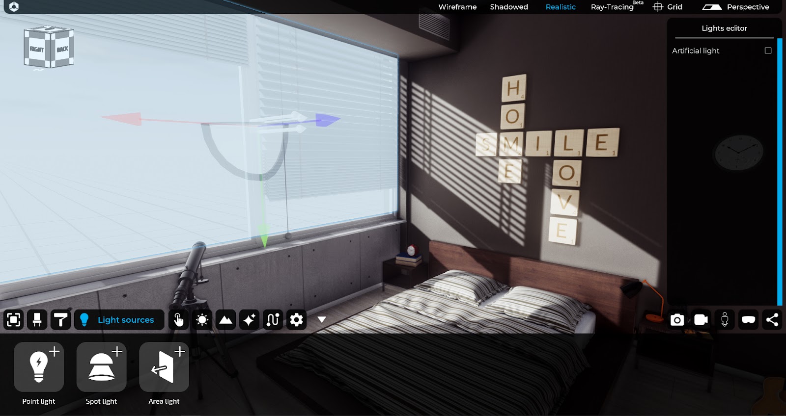
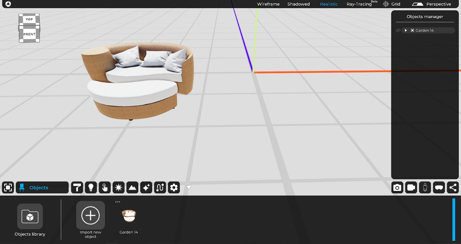
4. Light sources
The “Light sources” TAB allows you to choose between some types of artificial lights:
- Point light
- Spot light
- Area light (Sky portal or Artificial Area light)
To insert them into the current project, you can drag them from the menu into the scene from the grid, where you can change their position and parameters, via the contextual menu that is activated by selecting one of the lights in the scene.
For a detailed overview of the options related to the creation and modification of light sources, please refer to chapter 4 of this manual.
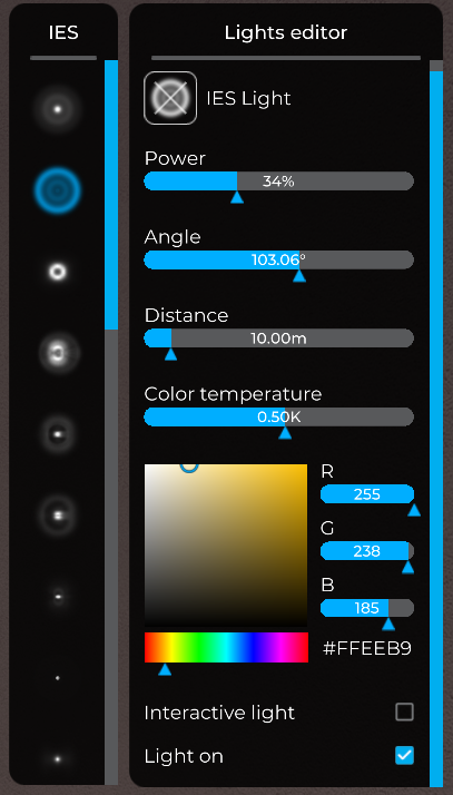
4.1 Point light
The point light is an omnidirectional point source that can be modified through the following parameters and settings:
- IES Light
- Power
- Angle
- Distance
- Color temperature

4.2 Spot-light
The spot-light is a point source that emits light through a conical projection, which can be modified through the following parameters and settings:
- IES Light
- Power
- Angle
- Distance
- Color temperature

4.3 Area-light
The area-light is a portal used to facilitate interior lighting. Its function is to project the ambient light component present in the scene. It is effective only in the direction of the vector’s arrow represented on the plane. The area-light can be configured in the dimensions of the top (width and height) and it is usually placed immediately inside the openings of the planned interiors.
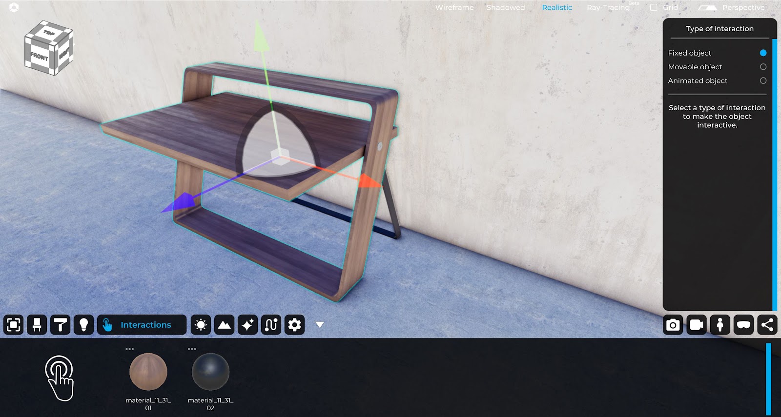
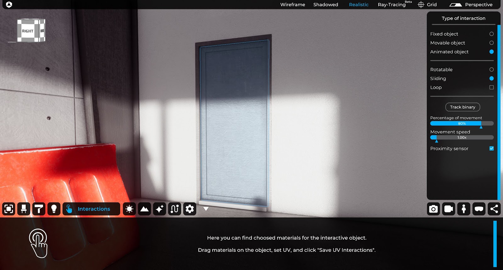
5. Interactions
The TAB “Interactions” allows to define the interactions of the objects present in the scene of the current project (3D space of Eyecad VR). The interactions are effective in the “exploration mode” to allow the user to open and close the openings, as well as to configure different alternative solutions in the project spaces.
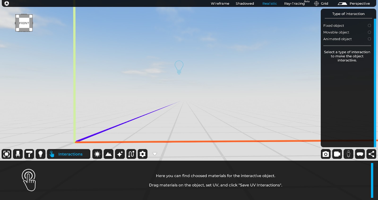
In Eyecad VR, the following types of interaction are available:
- Fixed object
- Movable object
- Animated object
For a detailed overview of the options related to the creation of interactions, please refer to chapter 5 of this manual.
5.1 Fixed object
The “fixed object” interaction (default condition) allows to make an object immovable in the “explorer mode”. When an object present in the scene is characterized by the interaction “Fixed object” the user cannot in any way change its position.
5.2 Movable object
The “movable object” interaction allows you to set the possibility of moving and rotating an object in the “explorer mode”.
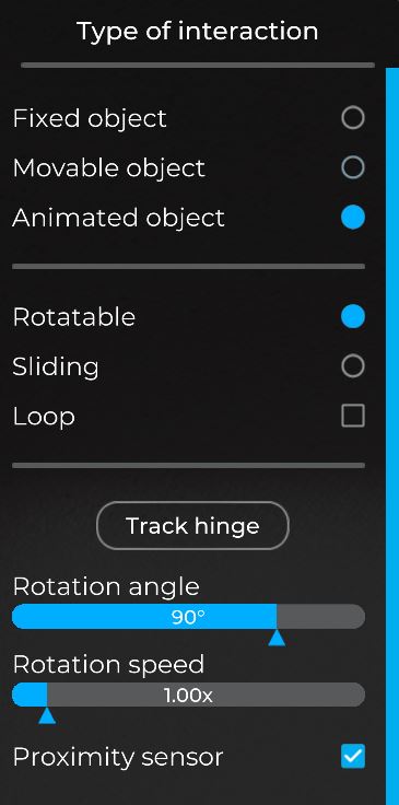
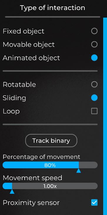
5.3 Animated Object
The “Animated object” interaction allows you to set the possibility to create a sliding movement or a rotation movement of an object in the “explorer mode”.
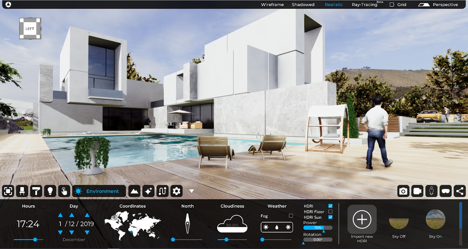
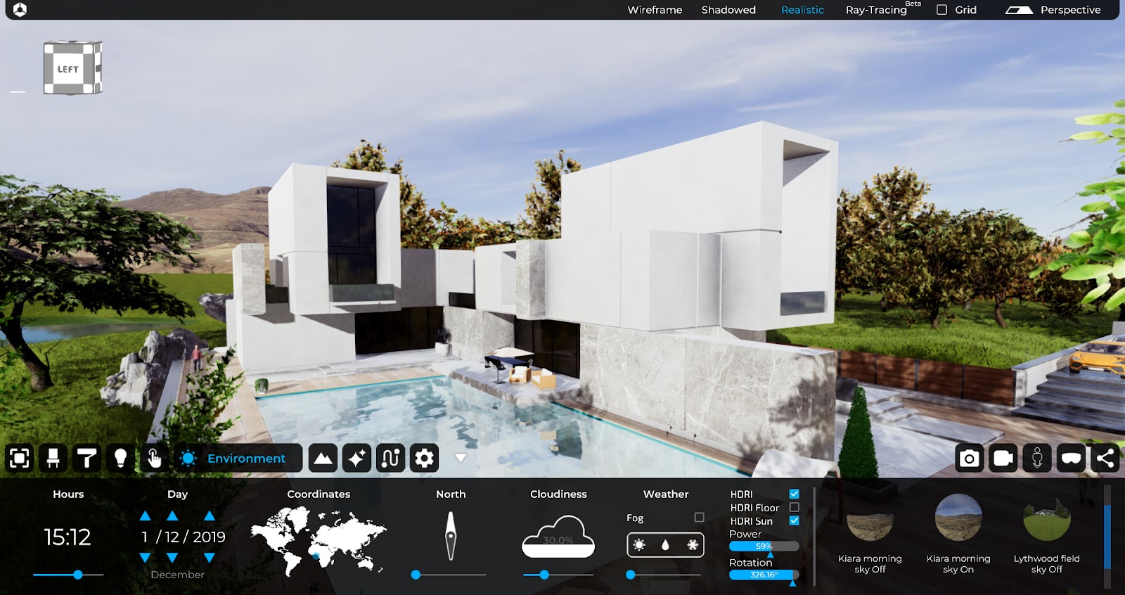
6. Environment
The “Environment” TAB allows you to set the configuration parameters relating to the light and visibility conditions of the current project, in addition to set the background and geolocate the scene in detail.

The “Environment” TAB is divided into the following configuration sub-menus:
- Hours
- Day
- Coordinates
- North
- Cloudiness
- Weather
- HDRI and Sky settings
6.1 Hours
The “Hours” function allows you to configure the day time, contextually changing the position of the sun in the scene. This function is related to the “Data” function.
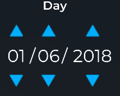
6.2 Day
The “Day” function allows you to set the current date of the project, contextually changing the position of the sun in the scene. This function is related to the “Time” function.
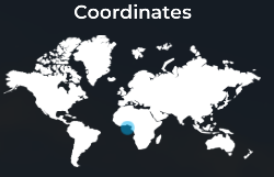
6.3 Coordinates
The “Coordinate” function allows you to set the terrestrial coordinates and geo-localize (optionally) the project. This function is related to the “Time” and “Day” functions and allows you to define the position of the sun in the scene.
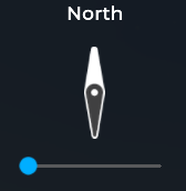
6.4 North
The “North” function allows you to set the position of the geographic north, thanks to that Eyecad VR is able to automatically determine the sunrise-sunset path, and to accurately determine its position in relation to the “Hours” functions, “Day” and “Coordinates”.
6.5 Cloudiness
The “cloudiness” function determines the amount of clouds in the project sky. The clouds are generated parametrically and affect the general shading of the scene. It is indicated in percentage terms (%).
6.6 Weather
It is indicated as a percentage, it determines the amount and type of precipitation that will affect the 3D scene.
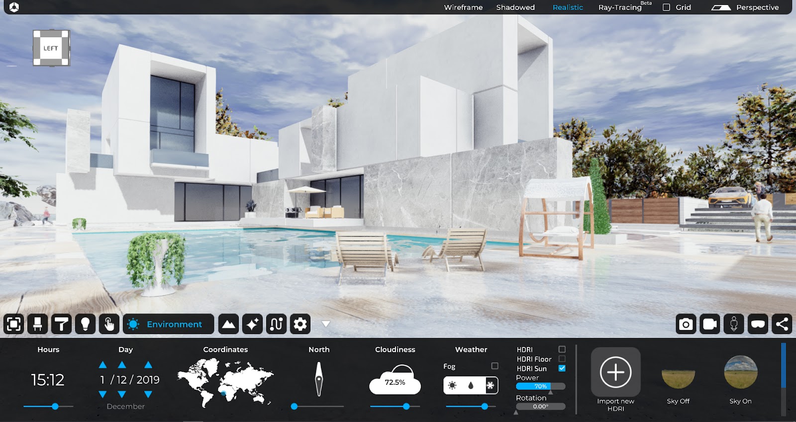
HDRI
The “HDRI” function allows to set the background of the scene, through the use of an HDRI 360 image, configurable in the following aspects:
o HDRI: it defines if the HDRI image must been on or off.
o HDRI Floor: it defines a virtual floor automatically generated from the HDRI.
o HDRI Sun: it allows to center the virtual Eyecad VR sun with the HDRI’s sun.
o Power: it controls the amount of light “Reflected” by the image itself. It influences on the surfaces and the overall environment.
o Rotation: it defines the rotation angle of the HDRI image with reference to the vertical axis (indicated in GREEN) of the 3D Eyecad VR scene.
For a detailed overview of the options related to the Environment tab, please refer to chapter 6 of this manual.
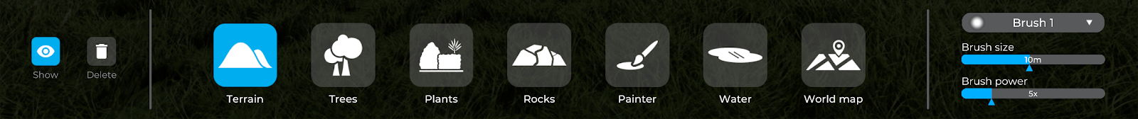
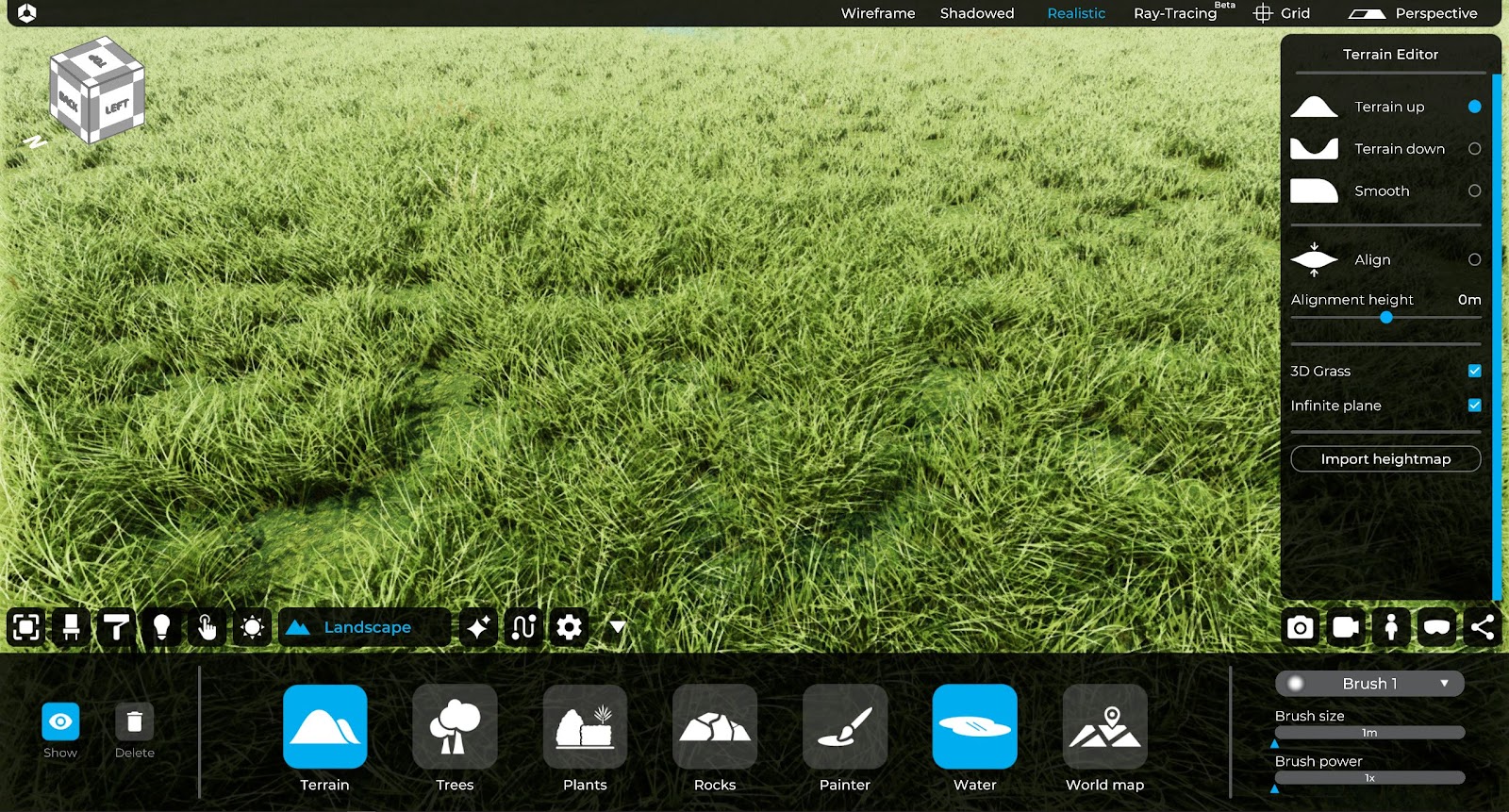
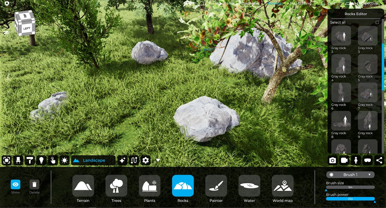
7. Landscape
The “Landscape” TAB allows to create and modify the elements of the natural or artificial landscape of the project, through the configuration of different parameters, referable to a specific function.
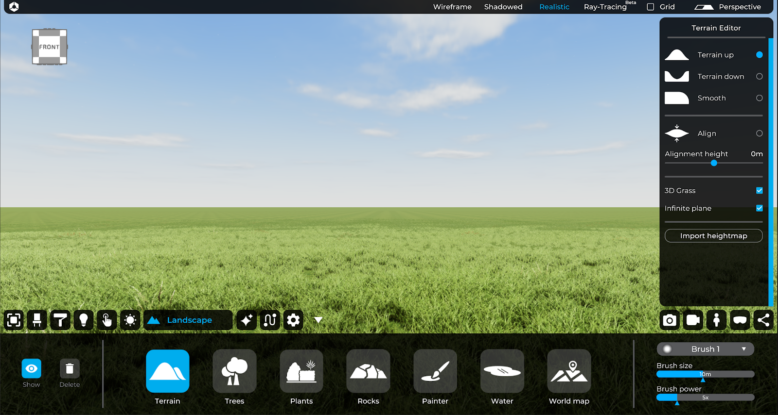
To activate the terrain editing commands, it is sufficient to click on the “Show” button in the “Landscape” TAB.
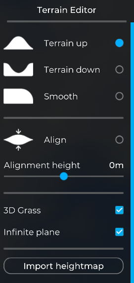
7.1 Terrain
The “terrain” function allows to modify the following modification parameters:
- Up: it allows to raise the ground in the portion of the area of modification.
- Down: it allows to lower the ground in the portion of the area of modification.
- Smooth: it makes the ground more uniform, natural and soft, damping angular points and accentuated disconnections in the modification area.
- Align: it leads to a single dimension in the brush area of the selected surface.
- 3D grass: it creates low 3D vegetation similar to reality with the dynamism of the wind movement giving more realism to the scene.
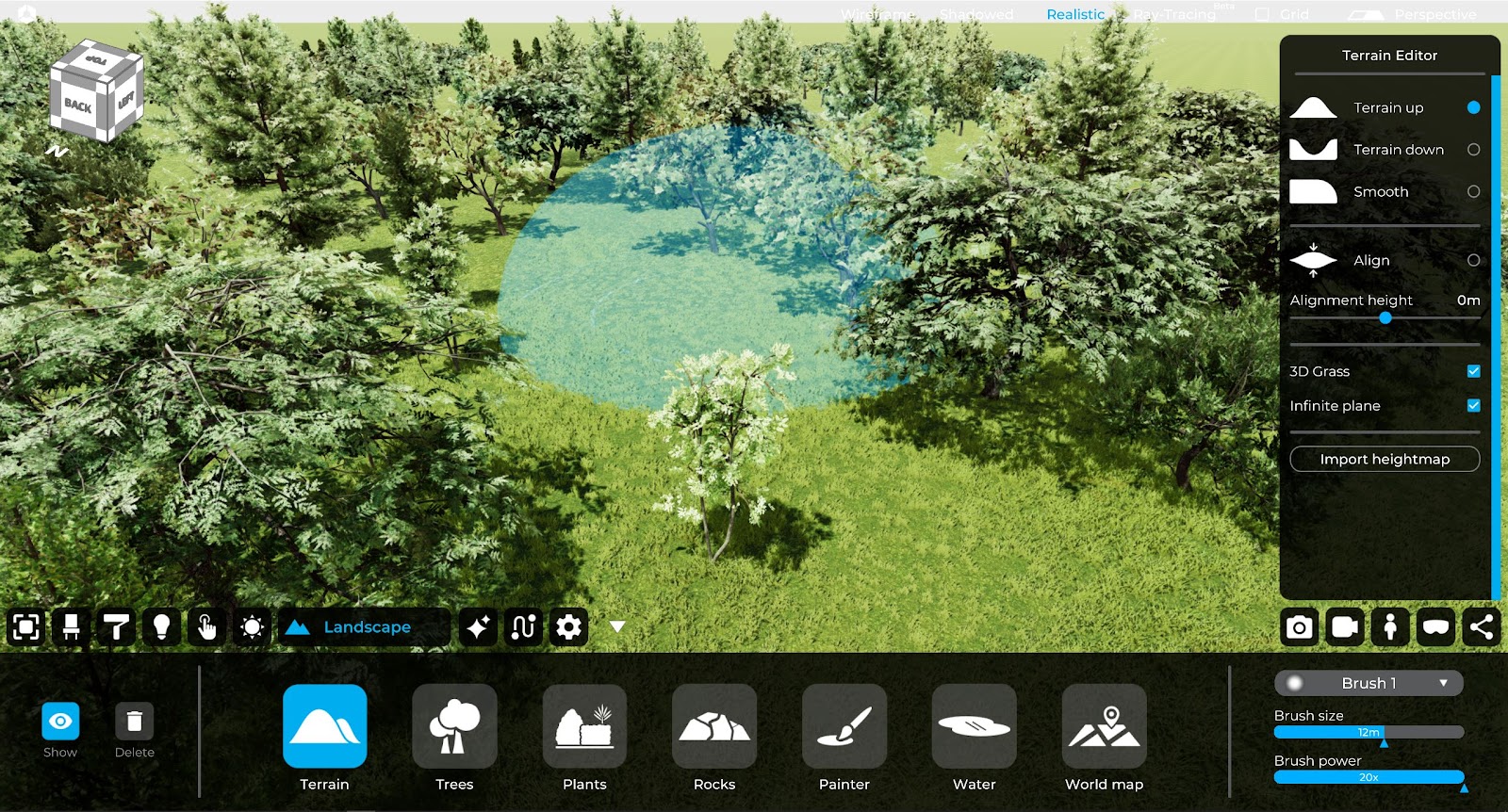
7.2 Trees
The “trees” function allows you to create and modify vegetation in the scene.
7.3 Plants
The “Plants” area allows you to add and modify garden vegetation in the scene.
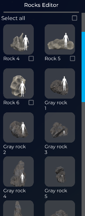
7.4 Rocks
It allows you to insert rocks inside the project.
7.5 Painter
The “brush” allows you to paint the areas of land subject to modification with the selected texture.
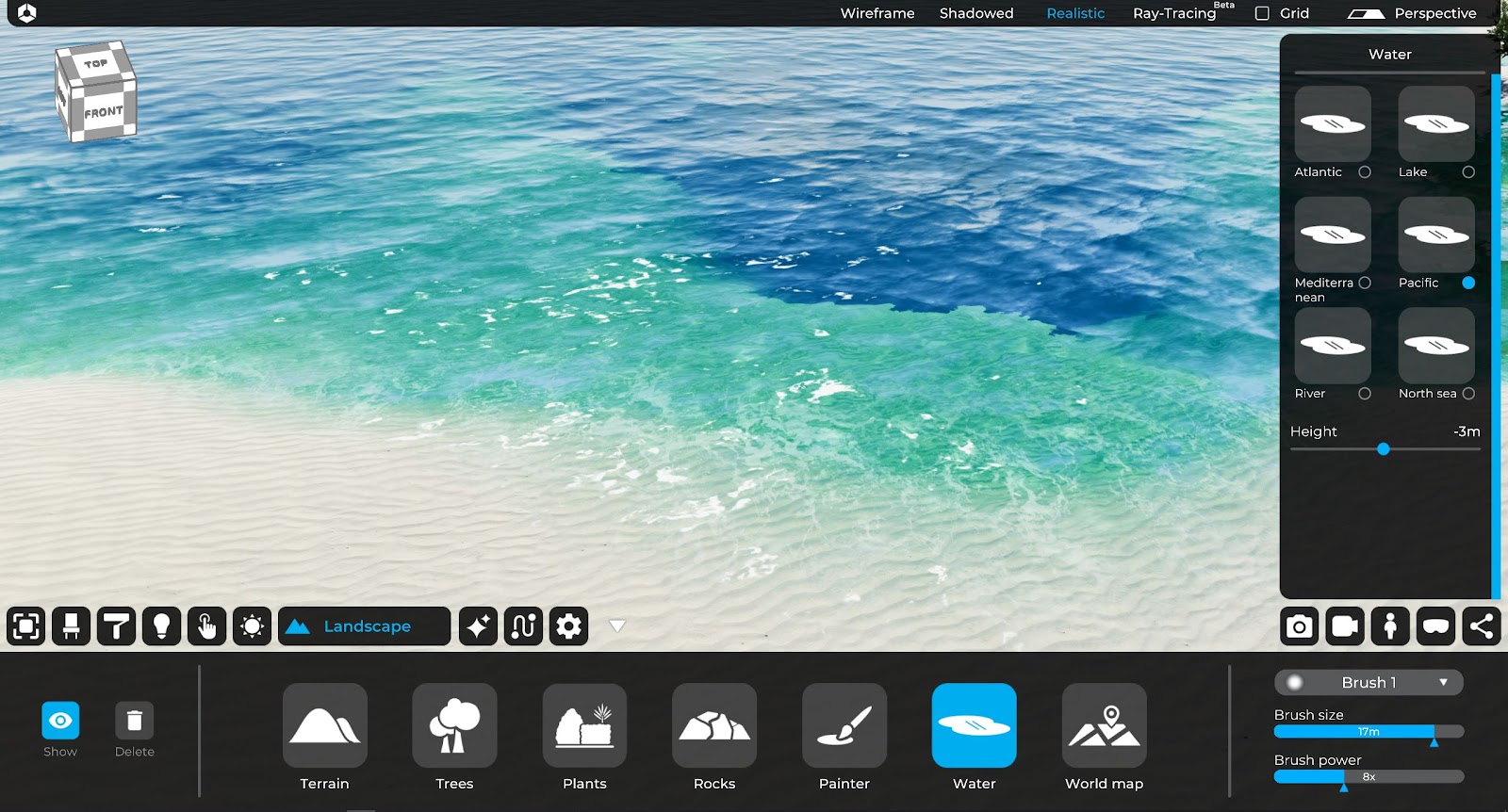
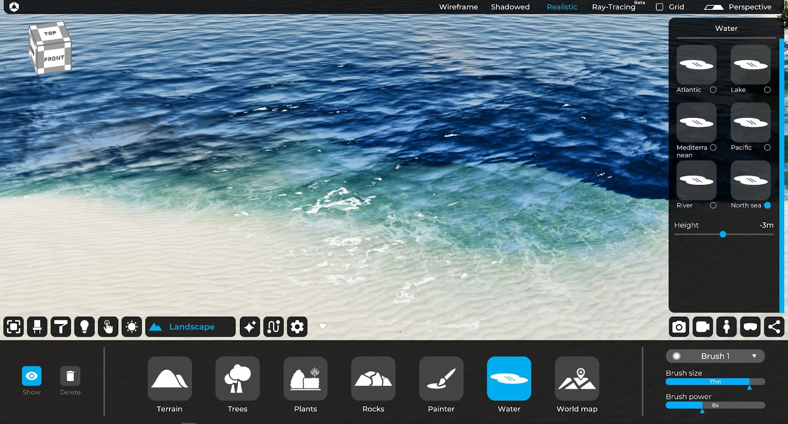
7.6 Water
Using a brush, you can choose the type of water to be used to highlight different characteristics of the soil according to your needs.
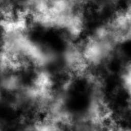
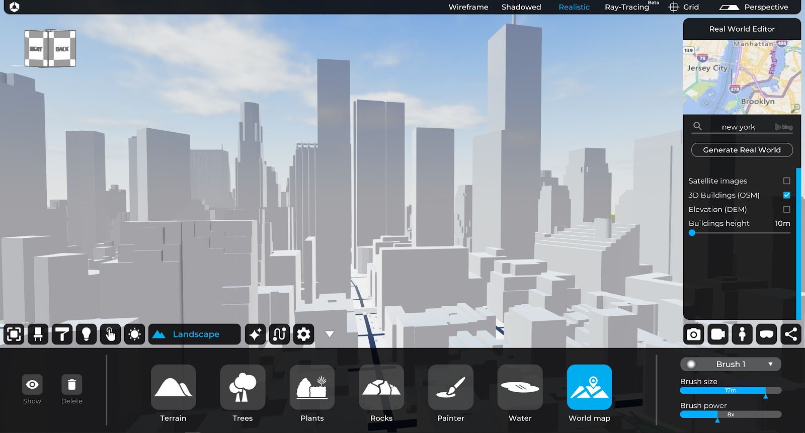
7.7 World map
It generates a relief map of the soil of a specific geographical area (Open Street Map + Digital Elevation Map).
For a detailed overview of the options related to the creation and modification of the 3D landscape, please refer to chapter 7 of this manual.
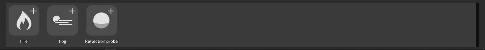
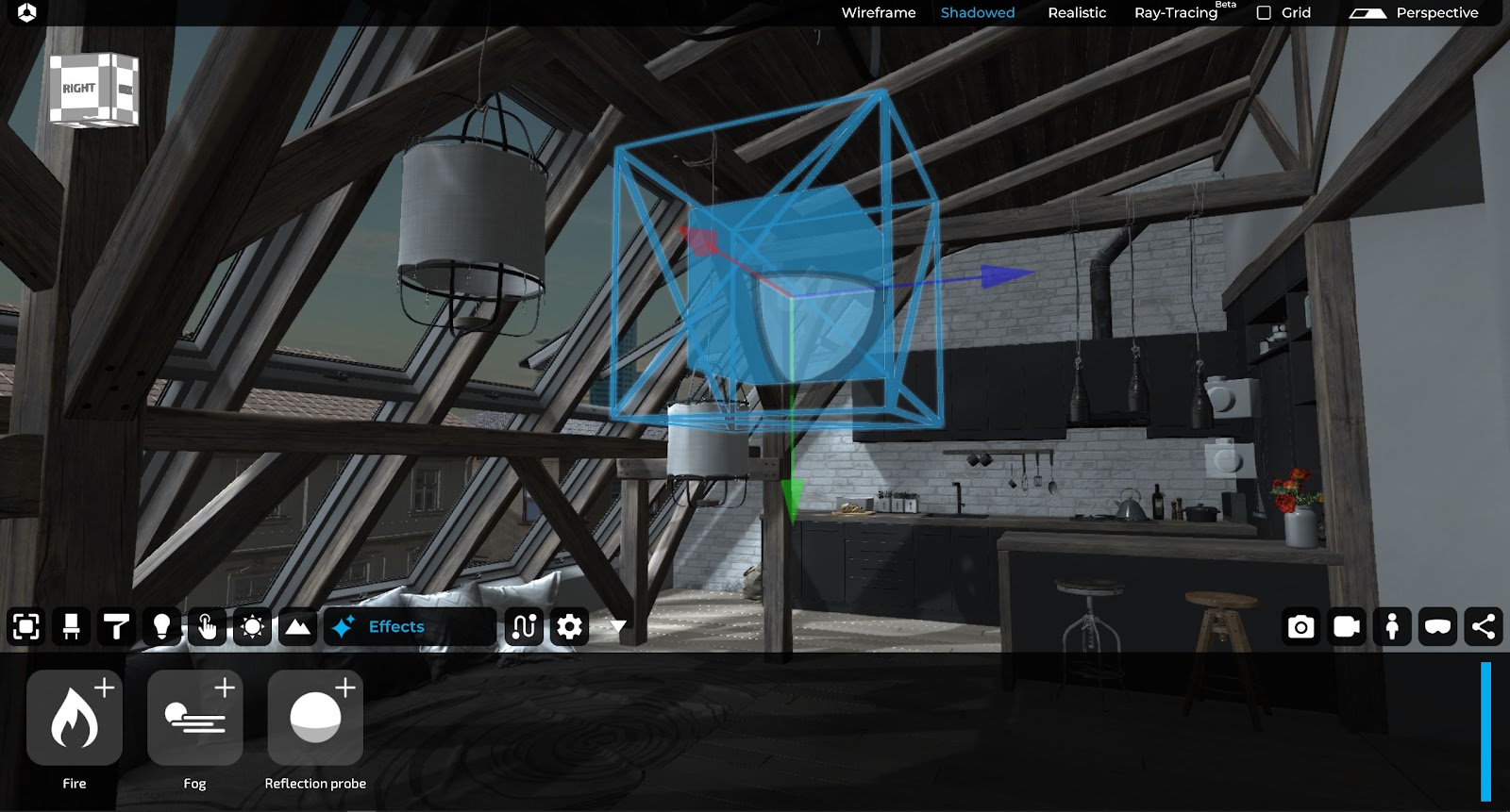
8. 3D visual effects

This tab allows you to insert different “animated” effects that make the project more realistic. These consist on:
- Fire: a 3D animation that generates the effect of a fireplace’s fire.
- Fog: a 3D animation that generates the mist haze effect.
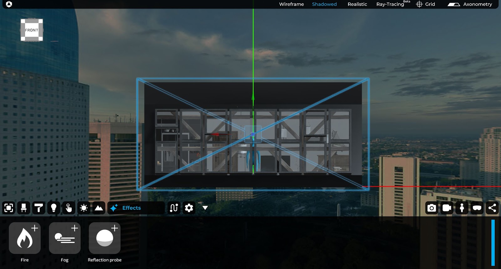
- Reflection probe: allows you to reflect objects and light on surfaces in a more realistic and real-time way.
For a detailed overview of the options related to the 3D visual effects, please refer to chapter 8 of this manual.
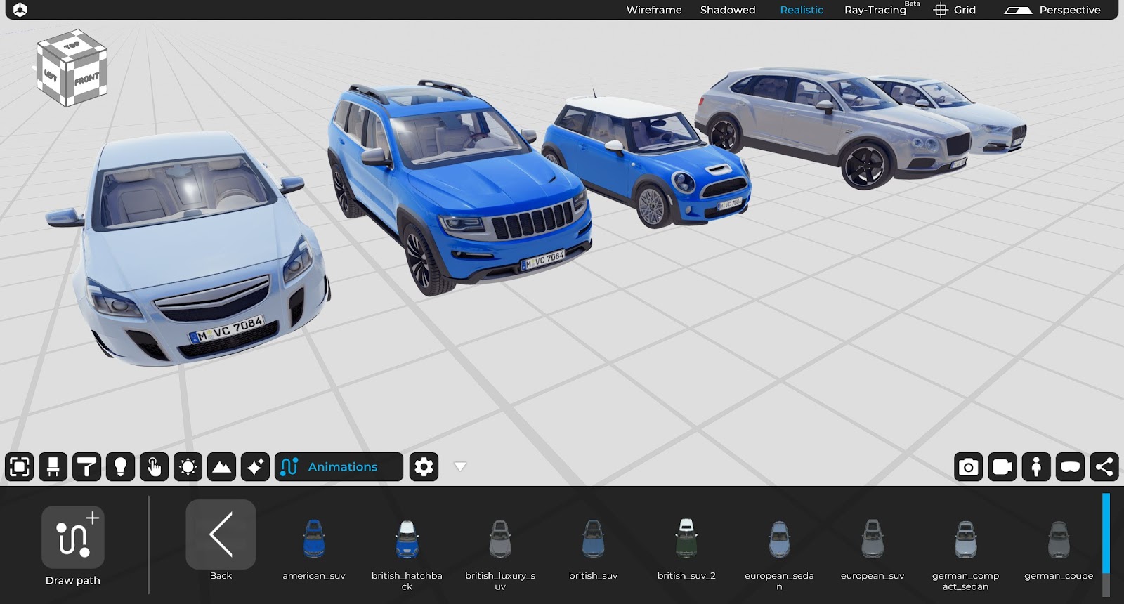
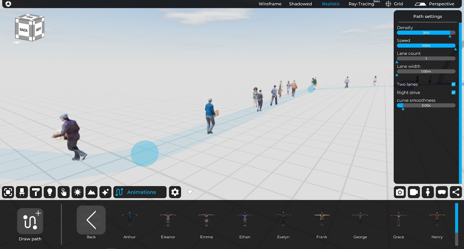
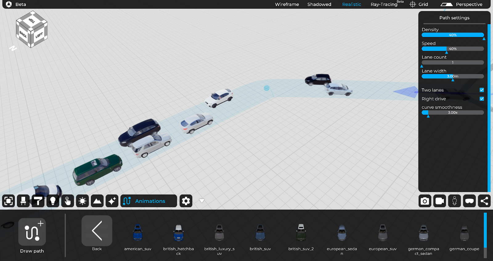
9. Animations
This TAB is designed to create path for animated 3D people and 3D vehicles.
For a detailed overview of the options related to the creation of 3D animations, please refer to chapter 9 of this manual.
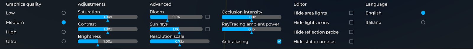
10. Settings
This TAB allows you to act on different display parameters and light effects, scale and other settings such as language.
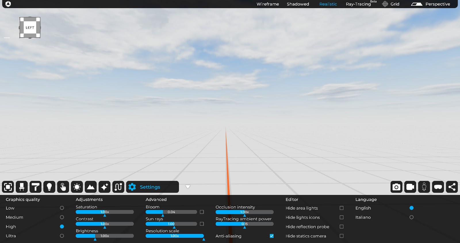
10.1 Graphics Quality
It affects the quality of effects, light, shadows and details:
10.2 Adjustments
It allows you to adjust various parameters such as:
- Saturation
- Contrast
- Brightness
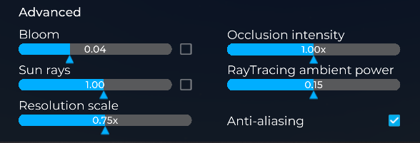
10.3 Advanced
Settings that affect the amount of light effects and the resolution scale.
- Bloom: it is an effect used in Computer Graphics with high dynamic range (HDR) rendering to reproduce an artifact of real-world camera images. The effect produces fringes (or feathers) of light that extend from the edges of the bright areas of an image, contributing to the illusion of extremely intense light that overwhelms the camera or the eye that captures the scene.
- Sun rays: accentuation of the penetration of sunlight into the scene.
- Anti aliasing: Anti-aliasing softens the lines by smoothing the edges and improving the quality of the image.
- Resolution scale: It manages image resolution and detail. For PCs that are not too fast, it is not recommended to increase the value of this parameter.
- Occlusion intensity: It defines the intensity of the environmental occlusion in the 3D scene.
- Ray Tracing Ambient Power: It defines the ambient intensity (only raytracing mode) of the 3D scene.
10.4 Editor
Selectable settings that allow:
- Hide Area-light: it hides the emitting surface but not the emitted light.
- Hide light icons: it hides the icons that indicate the presence of lights in the space.
- Hide refl. Probe: it hides the parallelepiped from the view but not the effects.
- Hide Static cameras
10.5 Language
It allows to set the language in different languages such as:
For a detailed overview of the options related to the settings tab, please refer to chapter 10 of this manual.
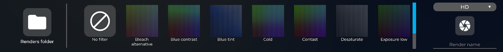
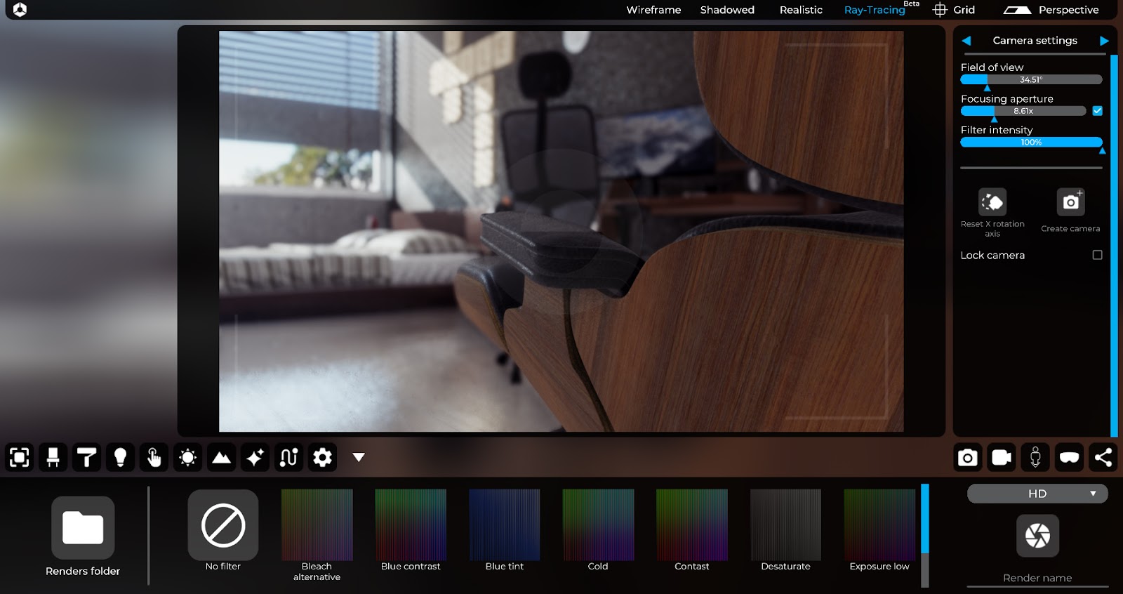
11. Render mode
This TAB allows you to shoot in few minutes, professional renders of your 3D projects in two different mode:
1- Realistic
2- Ray-Tracing

For a detailed overview of the options related to the creation of still images, please refer to chapter 11 of this manual.
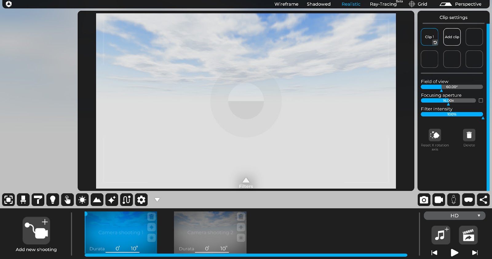
12. Video maker
This TAB allows you to create animated professional videos in few minutes with the most important camera settings clip by clip.
For a detailed overview of the options related to the creation and modification of videoclips, please refer to chapter 12 of this manual.
13. Starting position (exploration mode)
This TAB allows you to set the initial position of the 3D exploration (via monitor or via VR headsets).

13. Visualization options (exploration mode)
This TAB allows you to set the most important parameters for the exploration phase (via monitor or via VR headsets).
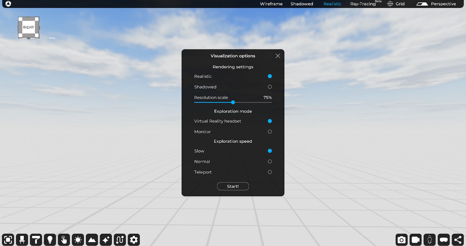
For a detailed overview of the options related to the exploration mode, please refer to chapter 13 of this manual.
14. Project sharing
This TAB allows you to share your 3D projects with your colleagues or customers.
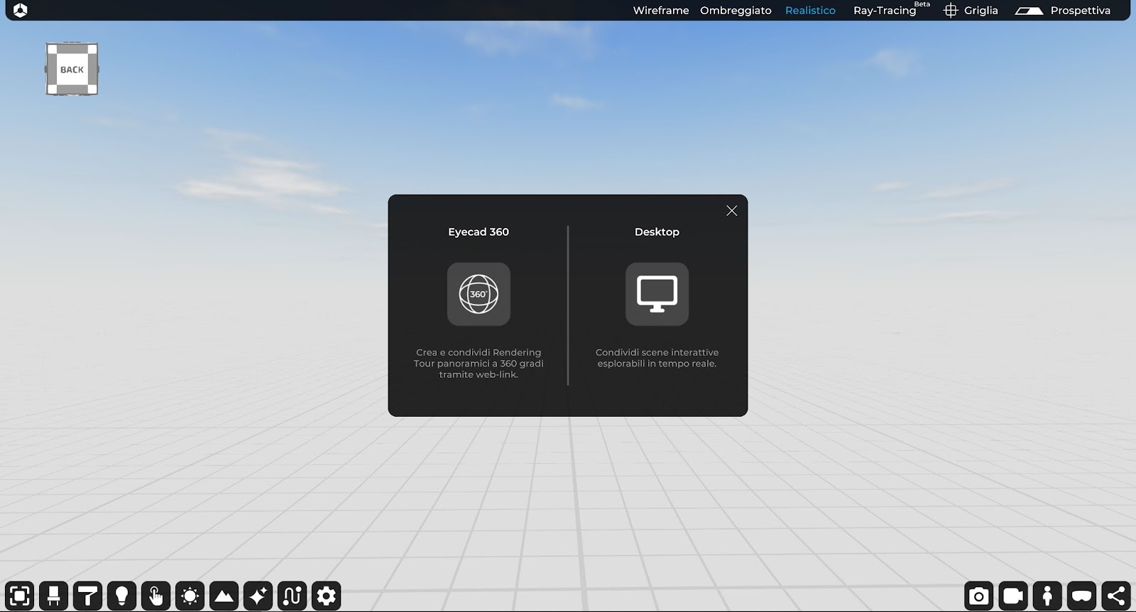
For a detailed overview of the options related to the Project sharing, please refer to chapter 14 of this manual.
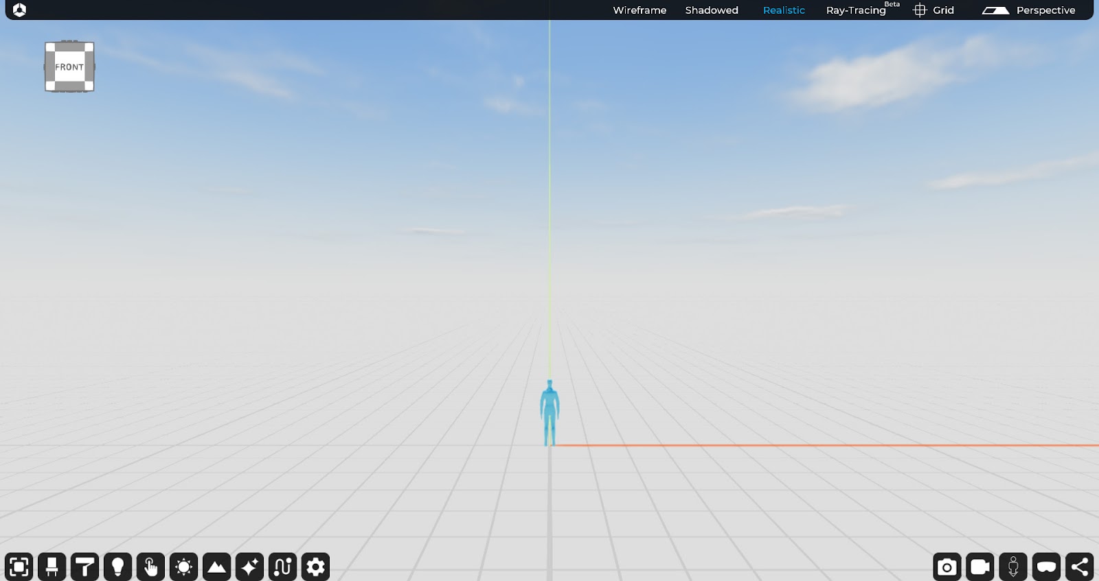
Visual Styles
Eyecad VR offers three types of visualization so you can to work to your project in a better way. The choice are:
- Wireframe: it is a type of computer graphic representation of three-dimensional objects. With this method only the edges of the object are represented as if it has been constructed with “wire”. This method requires easier calculations of the graphic processor rather than the representation of solid surfaces, and it is therefore considerably faster.
- Shadowed: shaded mode uses a mesh to shade surfaces without advanced rendering calculations.
- Realistic: it is the creation of an image starting from a mathematical description of a three-dimensional scene. It is interpreted by algorithms that define the color of each point of the digital image.
- Ray-Tracing (Beta): It is the new rendering mode that is more accurate and it works in real time in the Eyecad VR Editor.
For a detailed overview of the options related to the Ray-tracing mode please refer to chapter 15 of this manual.
Please note: the Ray-Tracing mode it works with efficient graphic cards like as Nvidia RTX series or GTX only 10th series.